ویم سسٹم کنٹرول ہدایات
مختصر تفصیل:
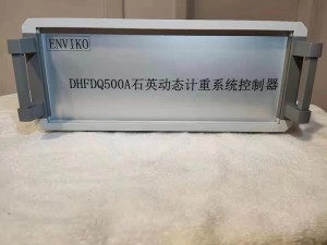
Enviko Wim Data Logger(Controller) متحرک وزنی سینسر (کوارٹج اور پیزو الیکٹرک)، گراؤنڈ سینسر کوائل (لیزر اینڈنگ ڈیٹیکٹر)، ایکسل شناخت کنندہ اور درجہ حرارت کے سینسر کا ڈیٹا اکٹھا کرتا ہے، اور انہیں گاڑیوں کی مکمل معلومات اور وزنی معلومات بشمول ایکسل کی قسم، وہیل نمبر، ایکسل نمبر، ٹائی ایکسل نمبر، وزن کی معلومات میں پروسیس کرتا ہے۔ وزن، کل وزن، اوور رن ریٹ، رفتار، درجہ حرارت، وغیرہ۔ یہ بیرونی گاڑی کی قسم شناخت کنندہ اور ایکسل شناخت کنندہ کو سپورٹ کرتا ہے، اور گاڑی کی قسم کی شناخت کے ساتھ گاڑی کی معلومات کا مکمل ڈیٹا اپ لوڈ یا اسٹوریج بنانے کے لیے سسٹم خود بخود میچ کرتا ہے۔
مصنوعات کی تفصیل
سسٹم کا جائزہ
Enviko کوارٹز متحرک وزن کا نظام ونڈوز 7 ایمبیڈڈ آپریٹنگ سسٹم، PC104 + بس توسیع پذیر بس اور وسیع درجہ حرارت کی سطح کے اجزاء کو اپناتا ہے۔ نظام بنیادی طور پر کنٹرولر، چارج یمپلیفائر اور IO کنٹرولر پر مشتمل ہے۔ یہ نظام متحرک وزنی سینسر (کوارٹج اور پیزو الیکٹرک)، گراؤنڈ سینسر کوائل (لیزر اینڈنگ ڈیٹیکٹر)، ایکسل شناخت کنندہ اور درجہ حرارت کے سینسر کا ڈیٹا اکٹھا کرتا ہے، اور ان پر گاڑی کی مکمل معلومات اور وزنی معلومات بشمول ایکسل کی قسم، ایکسل نمبر، وہیل بیس، ٹائر نمبر، ایکسل کی تعداد، وزن سے زیادہ درجہ حرارت، وزن کی رفتار، یہ سپورٹ گروپ کی رفتار، وزن وغیرہ وغیرہ کا ڈیٹا اکٹھا کرتا ہے۔ بیرونی گاڑی کی قسم کا شناخت کنندہ اور ایکسل شناخت کنندہ، اور نظام گاڑی کی قسم کی شناخت کے ساتھ مکمل گاڑی کی معلومات کا ڈیٹا اپ لوڈ یا اسٹوریج بنانے کے لیے خود بخود میچ کرتا ہے۔
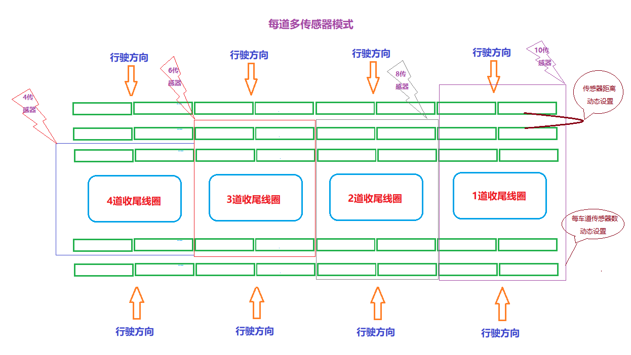
یہ نظام متعدد سینسر طریقوں کو سپورٹ کرتا ہے۔ ہر لین میں سینسرز کی تعداد 2 سے 16 تک سیٹ کی جا سکتی ہے۔ سسٹم میں چارج ایمپلیفائر امپورٹڈ، ڈومیسٹک اور ہائبرڈ سینسرز کو سپورٹ کرتا ہے۔ سسٹم کیمرہ کیپچر فنکشن کو متحرک کرنے کے لیے IO موڈ یا نیٹ ورک موڈ کو سپورٹ کرتا ہے، اور سسٹم سامنے، سامنے، دم اور ٹیل کیپچر کے کیپچر آؤٹ پٹ کنٹرول کو سپورٹ کرتا ہے۔
سسٹم میں ریاست کا پتہ لگانے کا کام ہے، نظام اصل وقت میں اہم سامان کی حیثیت کا پتہ لگا سکتا ہے، اور غیر معمولی حالات کی صورت میں خود بخود مرمت اور معلومات اپ لوڈ کر سکتا ہے۔ سسٹم میں خودکار ڈیٹا کیش کا کام ہے، جو تقریباً آدھے سال تک پتہ چلنے والی گاڑیوں کا ڈیٹا محفوظ کر سکتا ہے۔ سسٹم میں ریموٹ مانیٹرنگ، سپورٹ ریموٹ ڈیسک ٹاپ، ریڈمن اور دیگر ریموٹ آپریشن، سپورٹ ریموٹ پاور آف ری سیٹ کا کام ہے۔ سسٹم مختلف قسم کے تحفظ کے ذرائع استعمال کرتا ہے، بشمول تین سطحی WDT سپورٹ، FBWF سسٹم پروٹیکشن، سسٹم کیورنگ اینٹی وائرس سافٹ ویئر وغیرہ۔
تکنیکی پیرامیٹرز
| طاقت | AC220V 50Hz |
| رفتار کی حد | 0.5 کلومیٹر فی گھنٹہ~200 کلومیٹر فی گھنٹہ |
| سیل ڈویژن | ڈی = 50 کلوگرام |
| ایکسل رواداری | ±10% مستقل رفتار |
| گاڑی کی درستگی کی سطح | 5 کلاس، 10 کلاس، 2 کلاس(0.5 کلومیٹر فی گھنٹہ~20 کلومیٹر فی گھنٹہ) |
| گاڑیوں کی علیحدگی کی درستگی | ≥99% |
| گاڑی کی شناخت کی شرح | ≥98% |
| ایکسل بوجھ کی حد | 0.5t~40t |
| پروسیسنگ لین | 5 لین |
| سینسر چینل | 32 چینلز، یا 64 چینلز تک |
| سینسر لے آؤٹ | متعدد سینسر لے آؤٹ طریقوں کو سپورٹ کریں، ہر لین کو 2pcs یا 16pcs سینسر بھیجنے کے لیے، مختلف قسم کے پریشر سینسر کو سپورٹ کریں۔ |
| کیمرہ ٹرگر | 16 چینل DO الگ تھلگ آؤٹ پٹ ٹرگر یا نیٹ ورک ٹرگر موڈ |
| پتہ لگانے کا خاتمہ | 16 چینل ڈی آئی آئسولیشن ان پٹ کنیکٹ کوائل سگنل، لیزر اینڈنگ ڈیٹیکشن موڈ یا آٹو اینڈنگ موڈ۔ |
| سسٹم سافٹ ویئر | ایمبیڈڈ WIN7 آپریٹنگ سسٹم |
| ایکسل شناخت کنندہ تک رسائی | گاڑی کی مکمل معلومات بنانے کے لیے مختلف قسم کے وہیل ایکسل شناخت کنندہ (کوارٹج، انفراریڈ فوٹو الیکٹرک، عام) کو سپورٹ کریں |
| گاڑی کی قسم شناخت کنندہ تک رسائی | یہ گاڑی کی قسم کی شناخت کے نظام کو سپورٹ کرتا ہے اور لمبائی، چوڑائی اور اونچائی کے ڈیٹا کے ساتھ گاڑی کی مکمل معلومات تیار کرتا ہے۔ |
| دو طرفہ پتہ لگانے کی حمایت کریں۔ | دو طرفہ پتہ لگانے کو آگے اور ریورس کرنے میں مدد کریں۔ |
| ڈیوائس انٹرفیس | VGA انٹرفیس، نیٹ ورک انٹرفیس، USB انٹرفیس، RS232، وغیرہ |
| ریاست کا پتہ لگانا اور نگرانی کرنا | حالت کا پتہ لگانا: نظام اصل وقت میں اہم سامان کی حیثیت کا پتہ لگاتا ہے، اور غیر معمولی حالات کی صورت میں خود بخود مرمت اور معلومات اپ لوڈ کر سکتا ہے۔ |
| ریموٹ مانیٹرنگ: سپورٹ ریموٹ ڈیسک ٹاپ، ریڈمن اور دیگر ریموٹ آپریشنز، سپورٹ ریموٹ پاور آف ری سیٹ۔ | |
| ڈیٹا اسٹوریج | وسیع درجہ حرارت کی ٹھوس حالت ہارڈ ڈسک، سپورٹ ڈیٹا اسٹوریج، لاگنگ وغیرہ۔ |
| سسٹم کی حفاظت | تھری لیول ڈبلیو ڈی ٹی سپورٹ، ایف بی ڈبلیو ایف سسٹم پروٹیکشن، سسٹم کیورنگ اینٹی وائرس سافٹ ویئر۔ |
| سسٹم ہارڈویئر ماحول | وسیع درجہ حرارت صنعتی ڈیزائن |
| درجہ حرارت کنٹرول سسٹم | آلے کا اپنا درجہ حرارت کنٹرول سسٹم ہے، جو ریئل ٹائم میں آلات کے درجہ حرارت کی حالت کو مانیٹر کر سکتا ہے اور پنکھے کے شروع ہونے اور رکنے کو متحرک طور پر کنٹرول کر سکتا ہے۔ |
| ماحول کا استعمال کریں (وسیع درجہ حرارت کا ڈیزائن) | سروس درجہ حرارت: - 40 ~ 85 ℃ |
| رشتہ دار نمی: ≤ 85% RH | |
| پہلے سے گرم کرنے کا وقت: ≤ 1 منٹ |
ڈیوائس انٹرفیس
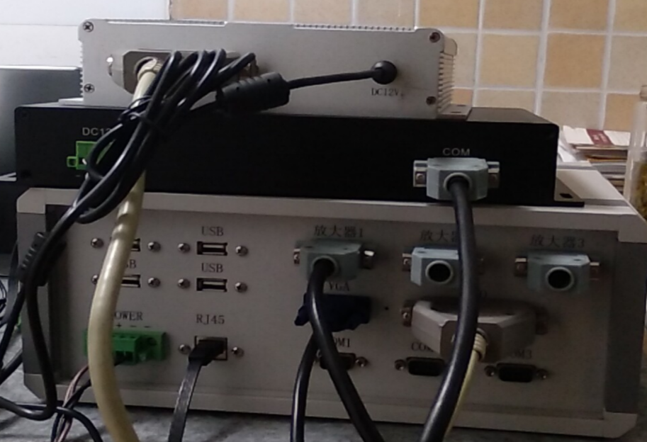
1.2.1 سسٹم کا سامان کنکشن
سسٹم کا سامان بنیادی طور پر سسٹم کنٹرولر، چارج ایمپلیفائر اور IO ان پٹ/آؤٹ پٹ کنٹرولر پر مشتمل ہوتا ہے۔
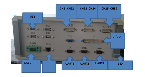
1.2.2 سسٹم کنٹرولر انٹرفیس
سسٹم کنٹرولر 3 چارج ایمپلیفائرز اور 1 IO کنٹرولر کو جوڑ سکتا ہے، 3 rs232/rs465، 4 USB اور 1 نیٹ ورک انٹرفیس کے ساتھ۔
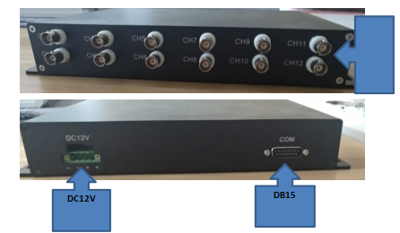
1.2.1 یمپلیفائر انٹرفیس
چارج ایمپلیفائر 4، 8، 12 چینلز (اختیاری) سینسر ان پٹ، DB15 انٹرفیس آؤٹ پٹ کو سپورٹ کرتا ہے، اور ورکنگ وولٹیج DC12V ہے۔
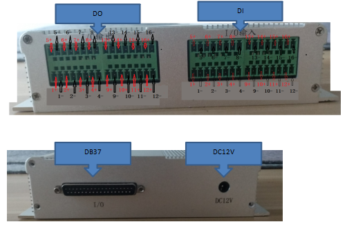
1.2.1 I/O کنٹرولر انٹرفیس
IO ان پٹ اور آؤٹ پٹ کنٹرولر، 16 الگ تھلگ ان پٹ، 16 آئسولیشن آؤٹ پٹ، DB37 آؤٹ پٹ انٹرفیس، ورکنگ وولٹیج DC12V کے ساتھ۔
نظام کی ترتیب
2.1 سینسر لے آؤٹ
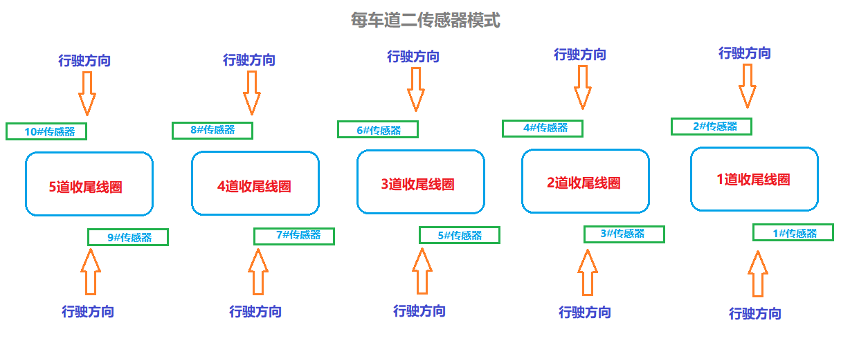
یہ متعدد سینسر لے آؤٹ طریقوں کو سپورٹ کرتا ہے جیسے کہ 2، 4، 6، 8 اور 10 فی لین، 5 لین تک، 32 سینسر ان پٹس (جس کو 64 تک بڑھایا جا سکتا ہے) کو سپورٹ کرتا ہے، اور فارورڈ اور ریورس دو طرفہ پتہ لگانے کے طریقوں کو سپورٹ کرتا ہے۔
ڈی آئی کنٹرول کنکشن
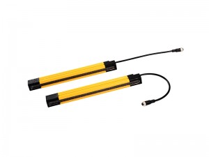
DI الگ تھلگ ان پٹ کے 16 چینلز، کوائل کنٹرولر، لیزر ڈیٹیکٹر اور دیگر فنشنگ آلات کو سپورٹ کرتے ہیں، ڈی موڈ کو سپورٹ کرتے ہیں جیسے کہ آپٹکوپلر یا ریلے ان پٹ۔ ہر لین کی آگے اور معکوس سمتیں ایک اختتامی ڈیوائس کا اشتراک کرتی ہیں، اور انٹرفیس کی وضاحت اس طرح کی گئی ہے۔
| اختتامی لین | DI انٹرفیس پورٹ نمبر | نوٹ |
| نمبر 1 لین (آگے، ریورس) | 1+،1- | اگر اختتامی کنٹرول ڈیوائس آپٹکوپلر آؤٹ پٹ ہے، تو اختتامی ڈیوائس کا سگنل ایک ایک کرکے IO کنٹرولر کے + اور - سگنلز کے مطابق ہونا چاہیے۔ |
| نمبر 2 لین (آگے، ریورس) | 2+،2- | |
| نمبر 3 لین (آگے، ریورس) | 3+،3- | |
| نمبر 4 لین (آگے، ریورس) | 4+،4- | |
| نمبر 5 لین (آگے، ریورس) | 5+،5- |
DO کنٹرول کنکشن
16 چینل ڈو الگ تھلگ آؤٹ پٹ، کیمرے کے ٹرگر کنٹرول، سپورٹ لیول ٹرگر اور گرتے ہوئے کنارے ٹرگر موڈ کو کنٹرول کرنے کے لیے استعمال کیا جاتا ہے۔ سسٹم خود فارورڈ موڈ اور ریورس موڈ کو سپورٹ کرتا ہے۔ فارورڈ موڈ کے ٹرگر کنٹرول اینڈ کو کنفیگر ہونے کے بعد، ریورس موڈ کو کنفیگر کرنے کی ضرورت نہیں ہے، اور سسٹم خود بخود بدل جاتا ہے۔ انٹرفیس کی وضاحت اس طرح کی گئی ہے:
| لین نمبر | فارورڈ ٹرگر | ٹیل ٹرگر | سائیڈ ڈائریکشن ٹرگر | دم کی طرف کی سمت کا محرک | نوٹ |
| نمبر 1 لین (آگے) | 1+،1- | 6+،6- | 11+،11- | 12+،12- | کیمرے کے ٹرگر کنٹرول اینڈ میں + - اینڈ ہوتا ہے۔ کیمرے کا ٹرگر کنٹرول اینڈ اور IO کنٹرولر کا + - سگنل ایک ایک کرکے مساوی ہونا چاہیے۔ |
| نمبر 2 لین (آگے) | 2+،2- | 7+،7- | |||
| نمبر 3 لین (آگے) | 3+،3- | 8+،8- | |||
| نمبر 4 لین (آگے) | 4+،4- | 9+،9- | |||
| نمبر 5 لین (آگے) | 5+،5- | 10+،10- | |||
| نمبر 1 لین (ریورس) | 6+،6- | 1+،1- | 12+،12- | 11+،11- |
سسٹم کے استعمال کا گائیڈ
3.1 ابتدائی
آلے کی ترتیب سے پہلے تیاری۔
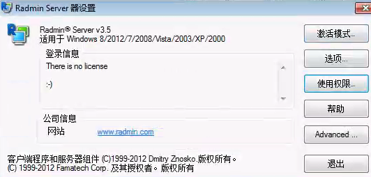
3.1.1 سیٹ Radmin
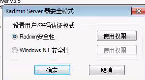
1) چیک کریں کہ آیا Radmin سرور انسٹرومنٹ (فیکٹری انسٹرومنٹ سسٹم) پر انسٹال ہے۔ اگر یہ غائب ہے تو براہ کرم اسے انسٹال کریں۔

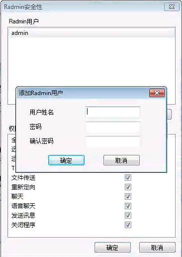
2) Radmin سیٹ کریں، اکاؤنٹ اور پاس ورڈ شامل کریں۔

3.1.2 سسٹم ڈسک کا تحفظ
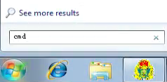
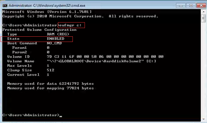
1) DOS ماحول میں داخل ہونے کے لیے CMD ہدایات کو چلانا۔
2) EWF تحفظ کی حیثیت سے استفسار کریں (ٹائپ کریں EWFMGR C: enter)
(1)اس وقت، EWF پروٹیکشن فنکشن آن ہے (State = ENABLE)
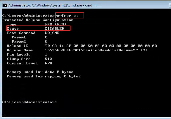
(ٹائپ کریں EWFMGR c: -communanddisable -live enter)، اور ریاست یہ بتانے کے لیے غیر فعال ہے کہ EWF تحفظ بند ہے۔
(2) اس وقت، EWF پروٹیکشن فنکشن بند ہو رہا ہے (state = disable)، بعد میں کسی آپریشن کی ضرورت نہیں ہے۔
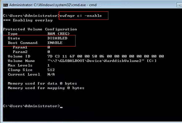
(3) سسٹم کی ترتیبات کو تبدیل کرنے کے بعد، EWF کو فعال کرنے کے لیے سیٹ کریں۔
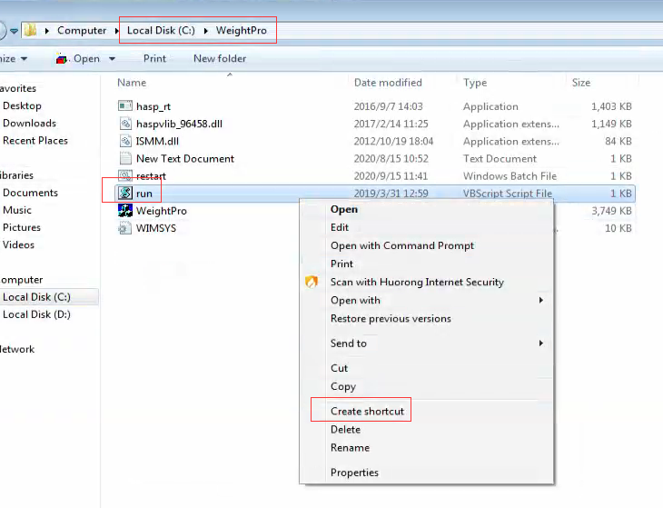
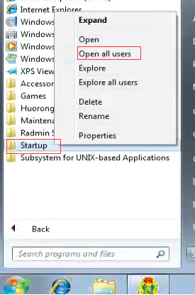
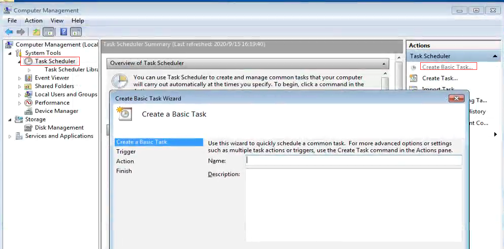
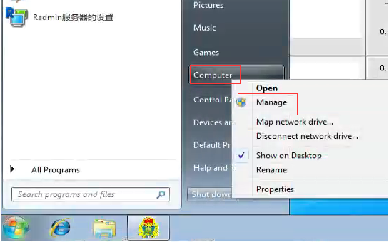
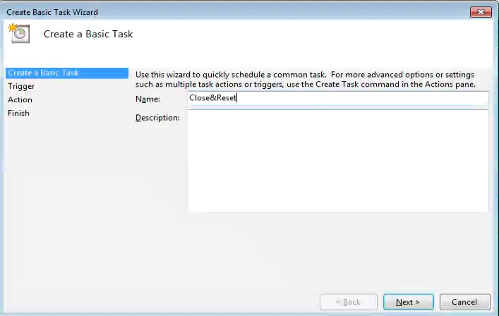
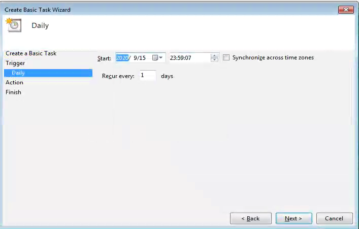
3.1.3 آٹو اسٹارٹ شارٹ کٹ بنائیں
1) چلانے کے لیے ایک شارٹ کٹ بنائیں۔

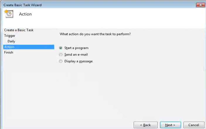
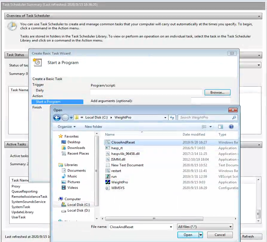
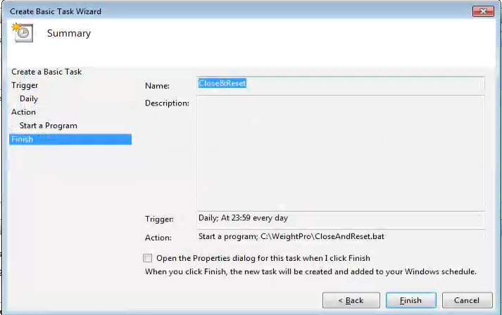
(2) پیرامیٹرز کی ترتیب
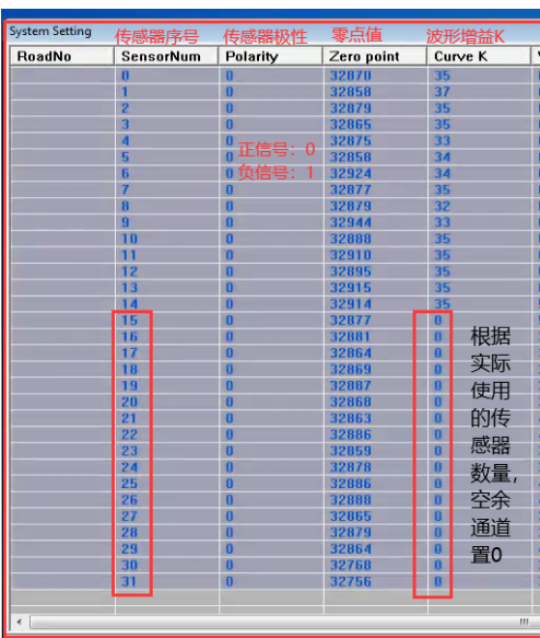
a. کل وزن کے گتانک کو 100 پر سیٹ کریں۔

b. IP اور پورٹ نمبر سیٹ کریں۔

c. نمونہ کی شرح اور چینل سیٹ کریں۔
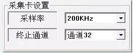
نوٹ: پروگرام کو اپ ڈیٹ کرتے وقت، براہ کرم نمونے لینے کی شرح اور چینل کو اصل پروگرام کے مطابق رکھیں۔
d. اسپیئر سینسر کی پیرامیٹر سیٹنگ

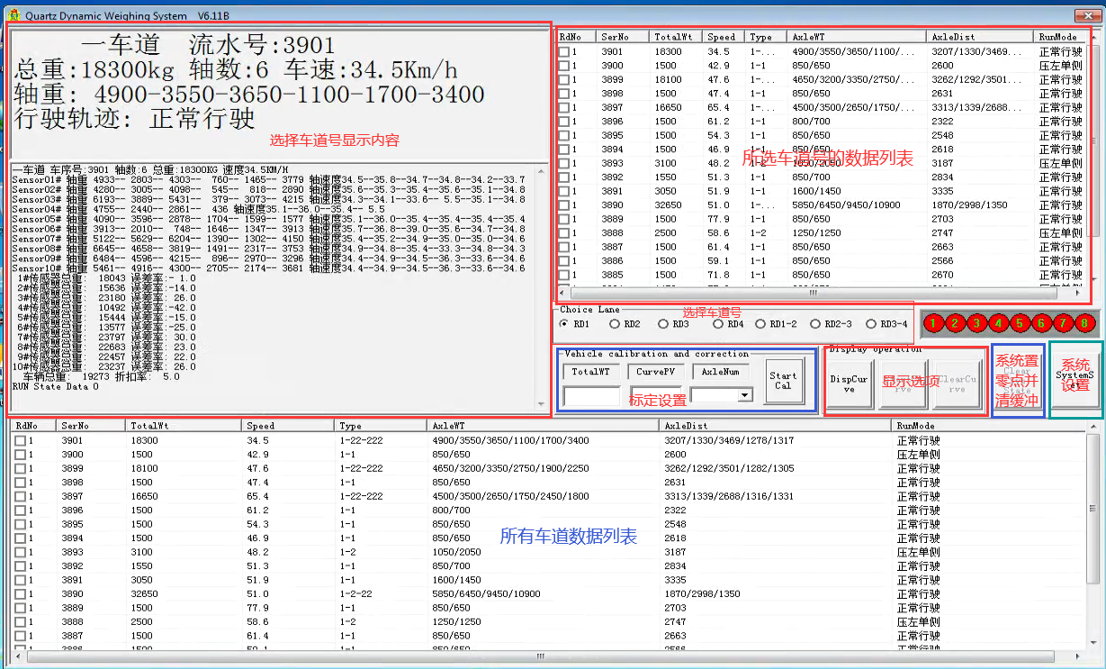
4. کیلیبریشن سیٹنگ درج کریں۔

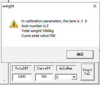
5. جب گاڑی سینسر کے علاقے سے یکساں طور پر گزرتی ہے (تجویز کردہ رفتار 10 ~ 15km/h ہے)، نظام وزن کے نئے پیرامیٹرز تیار کرتا ہے۔
6. نئے وزن کے پیرامیٹرز کو دوبارہ لوڈ کریں۔
(1) سسٹم کی ترتیبات درج کریں۔

(2) باہر نکلنے کے لیے محفوظ کریں پر کلک کریں۔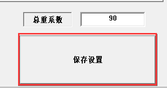
5. سسٹم کے پیرامیٹرز کی ٹھیک ٹیوننگ
جب معیاری گاڑی سسٹم سے گزرتی ہے تو ہر سینسر سے پیدا ہونے والے وزن کے مطابق، ہر سینسر کے وزن کے پیرامیٹرز کو دستی طور پر ایڈجسٹ کیا جاتا ہے۔
1. سسٹم سیٹ اپ کریں۔

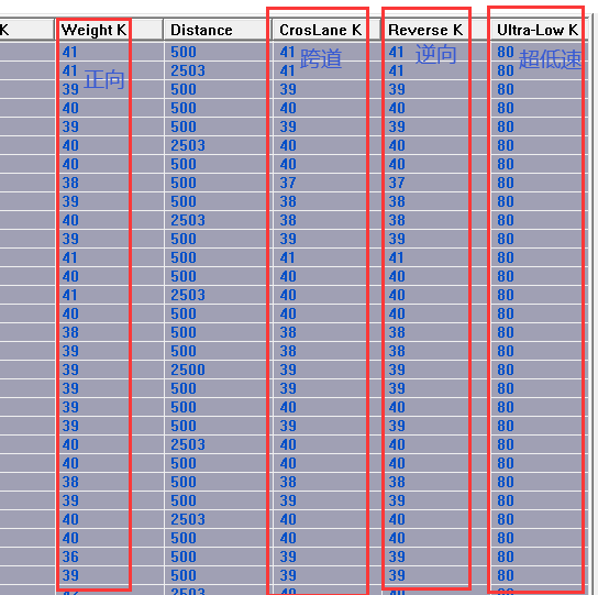
2. گاڑی کے ڈرائیونگ موڈ کے مطابق متعلقہ K-فیکٹر کو ایڈجسٹ کریں۔
وہ آگے، کراس چینل، ریورس اور انتہائی کم رفتار کے پیرامیٹرز ہیں۔
6. سسٹم کا پتہ لگانے کے پیرامیٹر کی ترتیب
سسٹم کا پتہ لگانے کی ضروریات کے مطابق متعلقہ پیرامیٹرز سیٹ کریں۔

سسٹم کمیونیکیشن پروٹوکول
TCPIP کمیونیکیشن موڈ، ڈیٹا ٹرانسمیشن کے لیے XML فارمیٹ کا نمونہ۔
- گاڑی میں داخل ہونا: آلہ مماثل مشین کو بھیجا جاتا ہے، اور مماثل مشین جواب نہیں دیتی ہے۔
| جاسوس سر | ڈیٹا باڈی کی لمبائی (8 بائٹ ٹیکسٹ کو انٹیجر میں تبدیل کیا گیا) | ڈیٹا باڈی (XML سٹرنگ) |
| DCYW | deviceno=آلہ نمبر roadno = سڑک نمبر recno=ڈیٹا سیریل نمبر /> |
- گاڑی چھوڑنا: آلہ ملاپ والی مشین کو بھیجا جاتا ہے، اور مماثل مشین جواب نہیں دیتی
| سر | (8 بائٹ متن کو عدد میں تبدیل کیا گیا) | ڈیٹا باڈی (XML سٹرنگ) |
| DCYW | deviceno=آلہ نمبر roadno = سڑک نمبر recno =ڈیٹا سیریل نمبر /> |
- وزن کا ڈیٹا اپ لوڈ کریں: آلہ مماثل مشین کو بھیجا جاتا ہے، اور مماثل مشین جواب نہیں دیتی ہے۔
| سر | (8 بائٹ متن کو عدد میں تبدیل کیا گیا) | ڈیٹا باڈی (XML سٹرنگ) |
| DCYW | deviceno=آلہ نمبر roadno = سڑک نمبر: recno=ڈیٹا سیریل نمبر kroadno = سڑک کے نشان کو عبور کرنا؛ 0 بھرنے کے لیے سڑک پار نہ کریں۔ رفتار = رفتار؛ یونٹ کلومیٹر فی گھنٹہ وزن =کل وزن: یونٹ: کلوگرام axlecount = محوروں کی تعداد؛ درجہ حرارت =درجہ حرارت; maxdistance=پہلے محور اور آخری محور کے درمیان فاصلہ، ملی میٹر میں axlestruct=ایکسل ڈھانچہ: مثال کے طور پر، 1-22 کا مطلب ہے پہلے ایکسل کے ہر طرف سنگل ٹائر، دوسرے ایکسل کے ہر طرف ڈبل ٹائر، تیسرے ایکسل کے ہر طرف ڈبل ٹائر، اور دوسرا ایکسل اور تیسرا ایکسل جڑے ہوئے ہیں۔ weightstruct=وزن کا ڈھانچہ: مثال کے طور پر، 4000809000 کا مطلب ہے پہلے ایکسل کے لیے 4000kg، دوسرے ایکسل کے لیے 8000kg اور تیسرے ایکسل کے لیے 9000kg فاصلاتی ساخت = فاصلہ کی ساخت: مثال کے طور پر، 40008000 کا مطلب ہے کہ پہلے محور اور دوسرے محور کے درمیان فاصلہ 4000 ملی میٹر ہے، اور دوسرے محور اور تیسرے محور کے درمیان فاصلہ 8000 ملی میٹر ہے۔ diff1=2000 گاڑی پر وزن کے ڈیٹا اور پہلے پریشر سینسر کے درمیان ملی سیکنڈ کا فرق ہے diff2=1000 گاڑی کے وزن کے ڈیٹا اور اختتام کے درمیان ملی سیکنڈ کا فرق ہے۔ لمبائی = 18000؛ گاڑی کی لمبائی؛ ملی میٹر چوڑائی = 2500؛ گاڑی کی چوڑائی؛ یونٹ: ملی میٹر اونچائی = 3500؛ گاڑی کی اونچائی؛ یونٹ ملی میٹر /> |
- سامان کی حیثیت: آلہ ملاپ والی مشین کو بھیجا جاتا ہے، اور مماثل مشین جواب نہیں دیتی ہے۔
| سر | (8 بائٹ متن کو عدد میں تبدیل کیا گیا) | ڈیٹا باڈی (XML سٹرنگ) |
| DCYW | deviceno=آلہ نمبر کوڈ="0" اسٹیٹس کوڈ، 0 نارمل کی نشاندہی کرتا ہے، دوسری قدریں غیر معمولی کی نشاندہی کرتی ہیں۔ msg="" ریاست کی تفصیل /> |
Enviko 10 سال سے زیادہ عرصے سے Weight-in-Motion Systems میں مہارت حاصل کر رہا ہے۔ ہمارے WIM سینسر اور دیگر مصنوعات ITS انڈسٹری میں بڑے پیمانے پر پہچانے جاتے ہیں۔


